Simples Machines
A machine is a device that allows a force (effort) applied at one point to overcome a resisting force (load) at another point.
Simple machines are devices that amplify or modify force, often at the expense of the distance through which the force is applied. Examples include:
- Levers
- Pulleys
- Inclined planes
- Wedges
- Wheel and axle
- Screw jack
Terms Used in Describing Machines
- Effort (E): The force applied to a machine.
- Load (L): The force of resistance that the machine overcomes.
- Mechanical Advantage (M.A): The ratio of load to effort. It is given by:
\[ M.A = \frac{\text{Load}}{\text{Effort}} \] - Velocity Ratio (V.R): The ratio of the distance moved by the effort to the distance moved by the load. It is independent of friction.
\[ V.R = \frac{\text{Distance moved by effort}}{\text{Distance moved by load}} \] - Efficiency (Ɛ): The ratio of useful work done by a machine to the work put into the machine. It is expressed as a percentage:
\[ \epsilon = \left(\frac{\text{Useful work done}}{\text{Work input}}\right) \times 100\% \] \[ \epsilon = \left(\frac{\text{Load} \times \text{Distance moved by load}}{\text{Effort} \times \text{Distance moved by effort}}\right) \times 100\% \] \[ \epsilon = \left(\frac{M.A}{V.R}\right) \times 100\% \]
A perfect machine has 100% efficiency, meaning M.A = V.R. However, in real machines, efficiency is always less than 100% due to friction.
Example
Problem: A machine with 80% efficiency is used to lift a 750 N load. If the velocity ratio is 4, calculate the effort required.
Solution:
- Load (L) = 750 N
- Efficiency (Ɛ) = 80%
- Velocity Ratio (V.R) = 4
Using the formula:
Ɛ = (M.A / V.R) × 100%
80/100 = M.A / 4
M.A = (80 × 4) / 100 = 3.2
Since M.A = Load / Effort:
Effort (E) = Load / M.A = 750 / 3.2 = 234.4 N
Types of Simple Machines
Levers
A lever is a simple machine that helps overcome large resistance using a small effort.
Classes of Levers
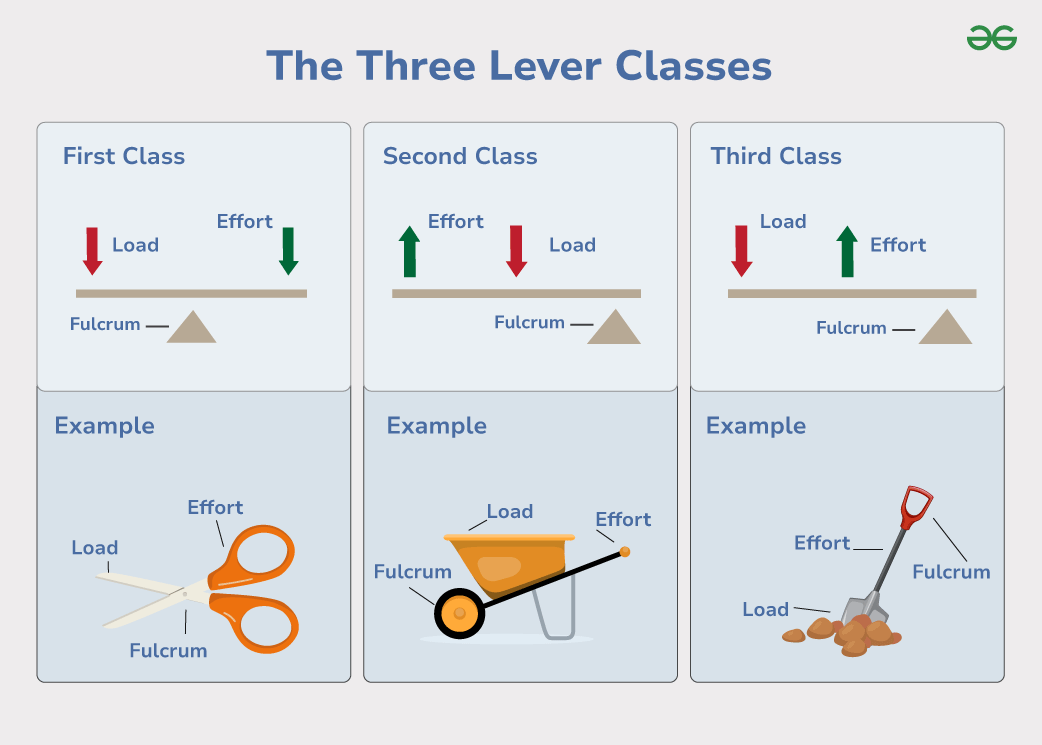
- First-Class Lever: The fulcrum is between the load and effort. Examples: scissors, crowbar, pliers.
- Second-Class Lever: The load is between the effort and the fulcrum. Examples: wheelbarrow, nutcrackers. (M.A and V.R are always greater than 1.)
- Third-Class Lever: The effort is between the load and fulcrum. Examples: forceps, tongs, forearm. (M.A and V.R are less than 1.)
 Credit: geeksforgeeks
Moments and Pulleys
Taking Moments About a Point
Taking the moment about point \( F \) gives:
\[ Y \times L = X \times E \] \[ L = \frac{E}{X} \] \[ Y = M.A = V.R \]
Pulleys
A simple pulley consists of a fixed wheel with a rope running around a groove in its rim. A load is attached to one end of the rope, and effort is applied to the other. If there is no friction, the load equals the effort, which equals the tension in the rope:
\[ L = T = E \]
Therefore, mechanical advantage (\( M.A \)) is equal to the velocity ratio (\( V.R \)):
\[ M.A = V.R \]
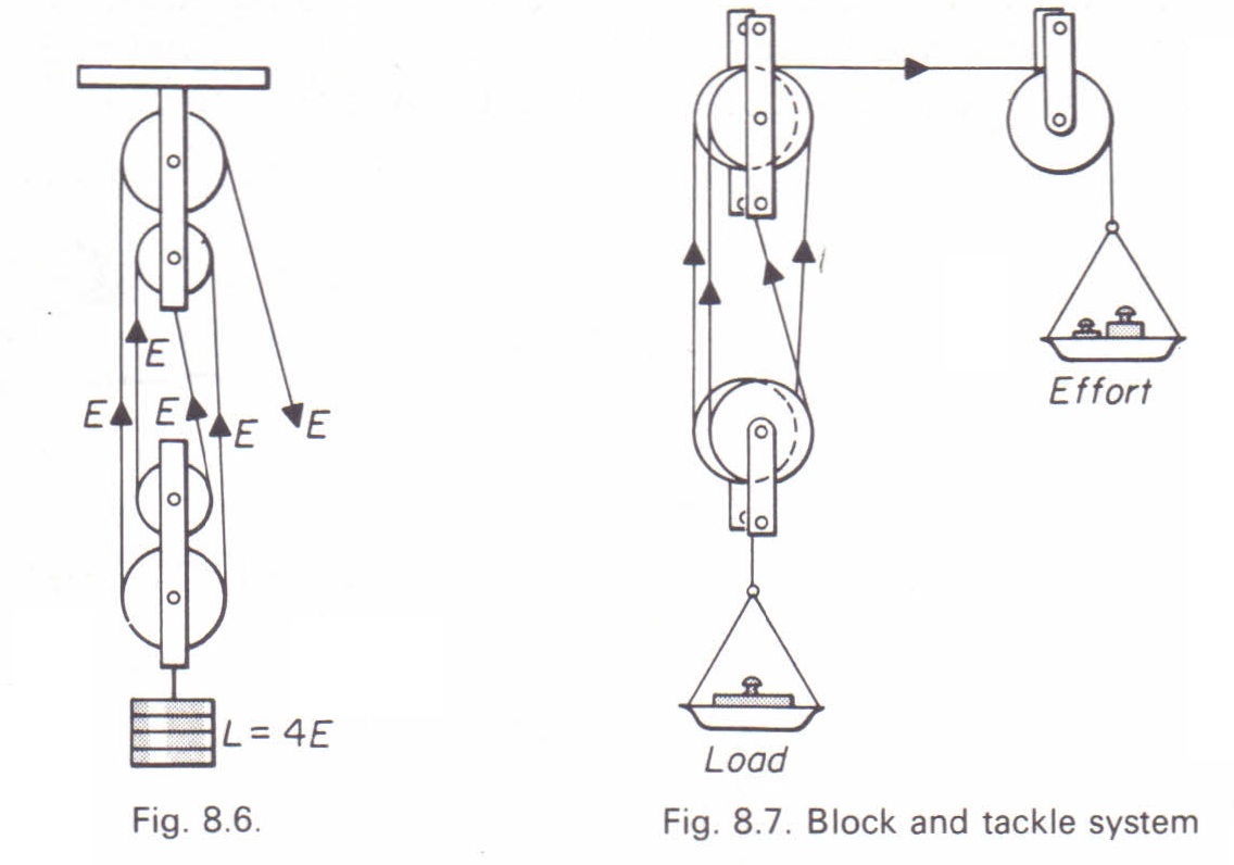
Block and Tackle System
For a system of pulleys with \( n \) pulleys, the velocity ratio is given by:
\[ V.R = n \]
Pulley systems are used for lifting heavy loads, such as in construction or shipping.
 Credit: PhysicsMax
Example
A pulley system has a velocity ratio of 6 and an efficiency of 80%. How much effort is required to lift a load of 120 kg? Assume \( g = 10 \, \text{m/s}^2 \).
Solution:
Given:
- \( V.R = 6 \)
- Efficiency = 80%
- Load = \( 1200N \)
- Effort = \( e \) (to be determined)
Efficiency is given by:
\[ \text{Efficiency} = \frac{M.A}{V.R} \times 100 \]
Substituting values:
\[ 80 = \frac{M.A}{6} \times 100 \]
\[ M.A = \frac{80 \times 6}{100} = 4.8 \]
Since:
\[ M.A = \frac{\text{Load}}{\text{Effort}} \]
The effort required is:
\[ \text{Effort} = \frac{\text{Load}}{M.A} = \frac{1200}{4.8} = 250N \]
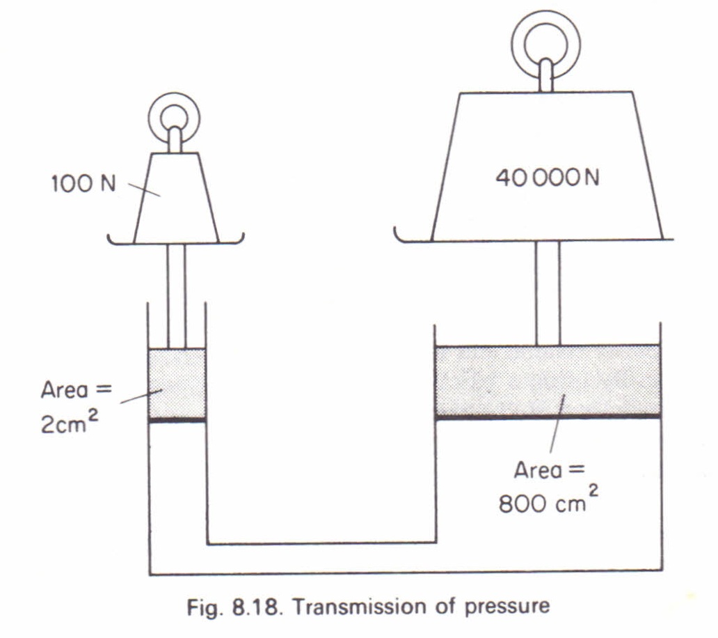
Hydraulic Press
A hydraulic press is a device used to generate a large force to compress or lift heavy loads. It is commonly used in printing presses to press ink onto paper. Pressure is transmitted equally in all directions in a liquid at the same level.
 Credit: PhysicsMax
If \( A_1 \) is the area of the smaller piston and \( A_2 \) is the area of the larger piston, then:
\[ P = \frac{E}{A_1}, \quad E = P \times A_1 \]
\[ P = \frac{L}{A_2}, \quad L = P \times A_2 \]
Thus, a small effort lifts a large load:
\[ M.A = \frac{L}{E} = \frac{A_2}{A_1} = \frac{R^2}{r^2} \]
If \( x \) and \( y \) are the distances moved by effort and load respectively, then:
\[ A_1 x = A_2 y \]
\[ \frac{x}{y} = \frac{A_2}{A_1} \]
Example
In a hydraulic press, a force of 40N is applied to a small piston with an area of \( 10 \text{cm}^2 \). If the larger piston has an area of \( 200 \text{cm}^2 \), calculate the force obtained.
Solution:
\[ M.A = \frac{L}{E} = \frac{A_2}{A_1} \]
\[ L = \frac{A_2}{A_1} \times E \]
Substituting values:
\[ L = \frac{200}{10} \times 40 = 800N \]
Thus, the force obtained is 800N.
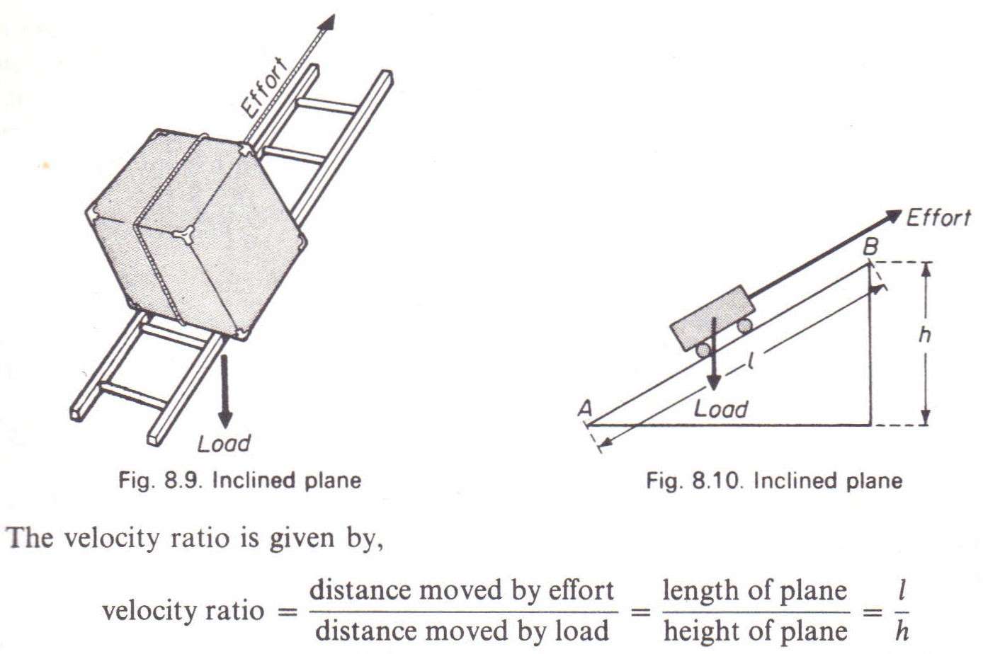
Inclined Plane
An inclined plane is used to move heavy loads up a slope, such as lifting oil drums onto a truck.
Its velocity ratio is given by:
$$ V.R = \frac{1}{sinθ} $$
 Credit: PhysicsMax
The Wedge
A wedge is essentially two inclined planes combined. It is used to separate objects held together by large forces, such as splitting timber.
Examples: axes, chisels, knives, and other cutting tools.
Screw
A screw is a mechanical fastening device consisting of an inclined plane wound spirally around a cylinder or cone. The ridges formed by the winding planes are called threads. Depending on the intended use, the threads may have square, triangular, or rounded cross-sections.
 Credit: PhysicsMax
Parts of a Screw Thread
A screw thread consists of the following parts:
- Thread or Lead: The distance along the screw’s axis that is covered by one complete rotation (360°) of the screw.
- Pitch: The distance between two corresponding points on adjacent threads.
-
Plane or Start: This determines whether a screw is single-start or double-start:
- Single-start: A single ridge is wrapped around the cylinder of the screw's body.
- Double-start: Two ridges are wrapped around the cylinder of the screw's body. With each complete rotation (360°), the screw advances axially by the width of two ridges.
Applications of Screws
Screws are commonly used in devices such as:
- Screw Jack: Used for lifting heavy loads.
- Ratchet Brace: A tool used for turning screws or drilling.
When a screw is turned through one complete revolution using an effort (such as on the screw head, the handle of a ratchet brace, or the tommy bar of a screw jack), the load moves a distance equal to the pitch \( P \), which is the distance between consecutive threads.
Velocity Ratio of a Screw
The velocity ratio (\( V.R \)) of a screw is given by:
\[ V.R = \frac{2\pi R}{P} \]
where:
- \( R \) = Radius of the screw or the length of the handle of the ratchet brace or tommy bar.
- \( P \) = Pitch of the screw (distance between consecutive threads).
If friction is negligible, then V.R = M.A.
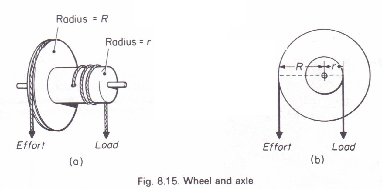
Wheel and Axle
A wheel and axle is a combination of two simple machines in one. It consists of a wheel mounted rigidly on an axle or drum of smaller diameter, both sharing the same axis. This device functions similarly to a lever, where:
- The wheel acts as the lever.
- The axle serves as the fulcrum.
 Credit: PhysicsMax
When a force is applied to the wheel, it transmits force to the axle, causing movement. If a rope is fixed onto the wheel and wound around it, leaving a free end where an effort \( E \) is applied, the rope attached to the axle is wound in the opposite direction, with the load attached to its free end. For each complete rotation of the wheel, the axle also completes one full rotation.
Velocity Ratio of a Wheel and Axle
Let \( R \) and \( r \) be the radii of the wheel and axle, respectively. The velocity ratio (\( V.R \)) is given by:
\[ V.R = \frac{\text{Distance moved by Effort}}{\text{Distance moved by Load}} = \frac{2\pi R}{2\pi r} = \frac{R}{r} \]
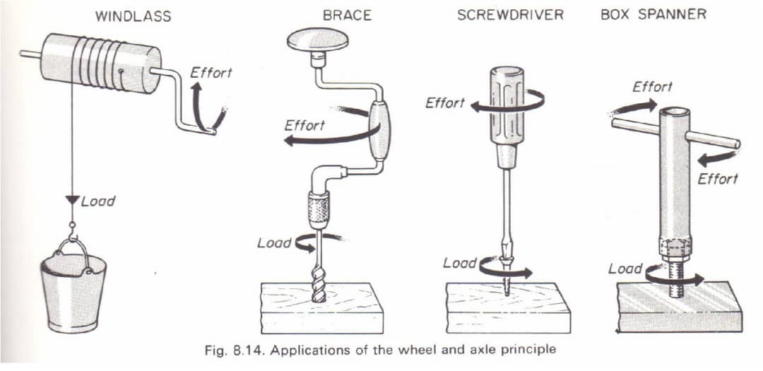
Applications of the Wheel and Axle
The wheel and axle mechanism is used in various applications, including:
- Steering wheel of an automobile
- Doorknob
- Windlass
- Treadmill
- Windmill
- Waterwheel
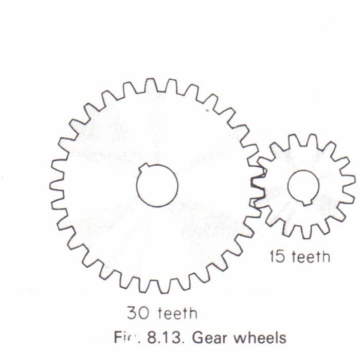
Gear Wheels
Gear wheels are commonly used in cars, bicycles, and cranes. They apply the principle of the wheel and axle, where two wheels of different sizes rotate together using a belt, chain, or interlocking gears.
 Credit: PhysicsMax
The velocity ratio for gears is given by:
$$ V.R = \frac{\text{Number of teeth on driven wheel}}{\text{Number of teeth on driving wheel}} $$